Usage Details
DB-25 Pinout - Inputs
| Pin(s) | Description |
|---|---|
| 1 | ADC Channel 0 |
| 2 | ADC Channel 1 |
| 3 | ADC Channel 2 |
| 4 | ADC Channel 3 |
| 5 | ADC Channel 4 |
| 6 | ADC Channel 5 |
| 7 | ADC Channel 6 |
| 8 | ADC Channel 7 |
| 9 | 5 volts |
| 10 | 5 volts |
| 11 | 5 volts |
| 12 | 5 volts |
| 13 | 5 volts |
| 14 | Ground |
| 15 | Ground |
| 16 | Ground |
| 17 | Ground |
| 18 | Ground |
| 19 | Ground |
| 20 | Ground |
| 21 | Ground |
| 22 | Ground |
| 23 | Ground |
| 24 | Ground |
| 25 | Ground |
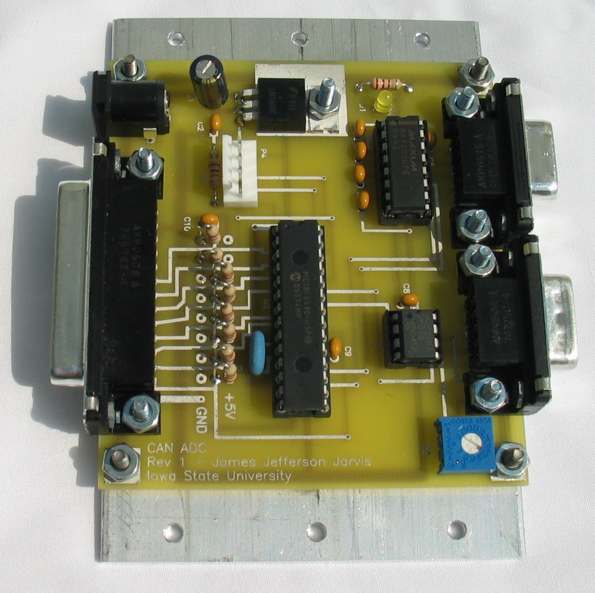
Technical Details
Bill Of Materials
| Designator(s) | Description | Part Number |
|---|---|---|
| U1 | CAN transceiver | MCP2551-I/P |
| U2 | PIC microcontroller | PIC18F2480-I/P |
| U3 | Voltage regulator, 5 volt | LM7805 |
| U4 | RS-232 transceiver | MAX202CPE |
| P1 | Power connector, 2.1x5.5mm | CP-201AH |
| P2 | RS-232 connector, DB9 female right angle | |
| P3 | CAN connector, DB9 male right angle | |
| P4 | In Circuit Serial Programming, 0.1" KK 5 position up | |
| P5 | Analog input connector, DB25 female right angle | |
| D1 | LED, T1 size | |
| R1 | Resistor, 330 ohm | |
| R2 | Potentiometer, 10k | Bourns 3386P |
| R3 | Resistor, 10k | |
| R10-R18 | Resistor, 2k (analog pull up or pull down) | |
| C1 | Capacitor, 100uF electrolytic | |
| C2-C10 | Capacitor, 0.1uF monolithic | |
| Y1 | Ceramic resonator, 4 MHz |
Parts without part number are non-critical.
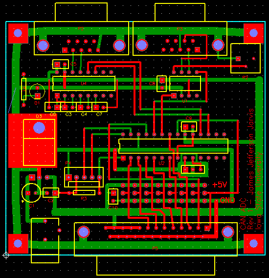
Printed Circuit Board
The CANADC circuit boards were laid out and manufactured using Pad2Pad. You'll need to install the Pad2Pad client to view or order CANADC boards.
- canadc.pcb 52k
Source Code and HEX Image
I wrote the software in C and used the PCH compiler from Custom Computer Services.- canadc.c Main source code
- canadc.hex Compiled hex file
You will also need to modify the can_set_baud() function to account for your processor speed and CAN bus parameters. I used "Microchip CAN Bit Timing Calculator" from Interpid Control Systems, Inc. to calculate the BRGCONx values. Then I just hardcoded them in to the can_set_baud() routine.
void can_set_baud(void) {
	/* 16 MHz, 250 kHz CAN bus */
	BRGCON1=0x01;
	BRGCON2=0xb8;
	BRGCON3=0x05;
}