Discontinued
The Temperature and Relative Humidity Sensor with Light Sensor has been discontinued. It has been replaced with our improved Temperature and Relative Humidity and our Solar Insolation sensor.
Introduction
This is a high quality, low cost, temperature and relative humidity sensor. Utilizing a pre-calibrated sensor element, it can measure temperature from -26°C to 70°C (-15°F to 158°F) and relative humidity from 3% to 100%. The sensor board provides an interface to a Davis Weather 6450 solar radiation sensor. The calibrated solar radiation sensor can measure 50 w/m^2 to 1800 w/m^2. The solar radiation sensor is not included with the basic sensor board.
The Temperature and Relative Humidity Sensor with Light Sensor Interface is compatible with our Wind Data Logger and WrenDAQ products.
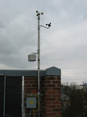
Photos of the sensor in action can be found in the photo gallery.
Specifications
| Temperature | |
|---|---|
| Range: | -27°C to 70°C |
| Accuracy: | ± 0.5°C typical |
| Response Time: | 50 seconds in slow moving air |
| Relative Humidity | |
| Range: | 3% to 100% non-condensing |
| Accuracy: | ± 2% RH typical | Linearity: | ± 0.5% RH |
| Hysteresis: | ± 1% RH, maximum |
| Temperature Coefficient: | ± 0.008% RH / °C, maximum |
| Hysteresis: | ± 1% RH, maximum |
| Response Time: | 25 seconds in slow moving air at 25°C |
| Recovery Time (from condensation): | 10 seconds |
| Stability: | ± 0.5% RH per year |
| Light Intensity (dependent on external sensor) | |
| Range: | 50 w/m^2 to 1800 w/m^2 |
| Accuracy: | ± 5% of full scale |
| Stability: | ± 2% per year |
| Weight and Dimensions | |
| Weight: | 20 grams (0.7 ounces) |
| Dimensions: | 35 mm wide, 83 mm tall, 20 mm deep (1.375 x 3.275 x 0.8 in) |
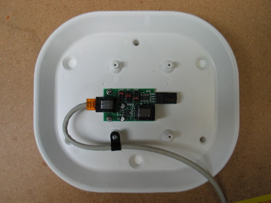
Mounting
The sensor is supplied as a bare printed circuit board and must be protected from the elements before installing outdoors. For maximum protection and sensor accuracy, we recommend that a solar radiation shield be used. The radiation shield provides shade and airflow over the sensor element without allowing rain to contact the circuit board. There are many manufacturers of radiation shields. We have used and can recommend Davis's or Ambient Weather's radiation shield. We sell Ambient Weather's.
|
|
If the sensor will be used near salt water or other corrosive gasses we can apply a conformal coating to further prevent corrosion. There is a small charge for this service.
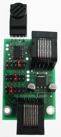
Wind Data Logger Configuration
The tempRhLight is plugged into the "TEMP&ADC" connector on the Wind Data Logger using a straight through cable / patch cord. If you wish to use the included temperature sensor you should use an 8Y splitter. The jumpers on the tempRhLight (shown in red on the above photo) determine which ADC channel each sensor is hooked to. Typically the relative humidity is on channel 0, temperature on channel 1, and light on channel 2. If you don't wish to use a sensor output you should leave the respective jumper off.
To display actual sensor readings on the Wind Data Logger you will need to configure the ADC channels. The following equations are used to convert the voltage output from the sensors to standard units:
Temperature:
°C=39.394*Vin - 30.0 (ADC M: 39.394 / ADC B: -30.0 / ADC Units: C)°F=70.9092*Vin - 22.0 (ADC M: 70.9092 / ADC B: -22.0 / ADC Units: F)
Relative Humidity:
%RH=30.303*Vin (ADC M: 30.303 / ADC B: +0.0 / ADC Units: %)Light Intensity:
watts / meter^2=598.802*Vin (ADC M: 598.802 / ADC B: +0.0 / ADC Units: W)The values in parenthesis should be entered into the ADC setup screens on the Wind Data Logger.
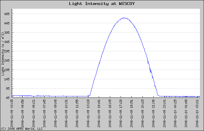
Example Data
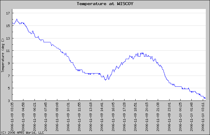
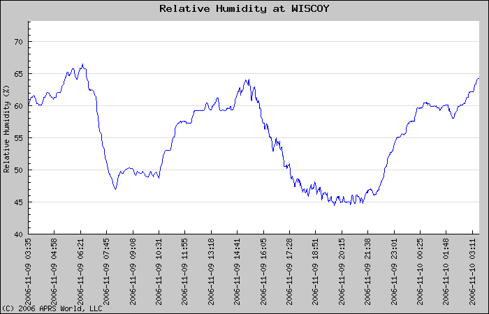
The following data was capture on 2006-11-09 near Winona, Minnesota, USA. Weather conditions observed at the local airport can be found at:http://www.wunderground.com/history/airport/KONA/2006/11/9/DailyHistory.html
Note that the local airport is approximately 15 miles distant.
Temperature Plot
Relative Humidity Plot
Solar Insolation