|
|
Introduction
The WrenDAQ2 is a compact, turbine top data acquisition unit. It is designed to transmit critical performance data for small turbine developers and testers. The standard WrenDAQ2 uses a license free 900 MHz data modem (for North American use only) to transfer data to your PC. Because the WrenDAQ2 is powered by the DC voltage from your turbine there are no additional cables to run; this allows adding data acquisition without adding additional slip rings for the signals.
The WrenDAQ2, by itself, does not log any data. A remote PC with wireless modem is required to log data. Our Wind2DB software can capture data from the WrenDAQ2. The WrenDAQ2 can be synchronized with our Wind Data Logger so that both sample at the same time.
Live data on the Internet!
One very neat feature of the WrenDAQ2 / Wind2DB package is that real time data from the WrenDAQ2 can be made available on the Internet. To use this feature you must have an always on Internet connection at your test site. An Internet server with appropriate software is also required. APRS World can provide this Internet service for a nominal fee. You can see an archived example of this Internet data service in the frame to your right. As part of the setup fee we will configure your WrenDAQ2 web page to display the parameters you are interested in with the format that you need.
Example data from a WrenDAQ2
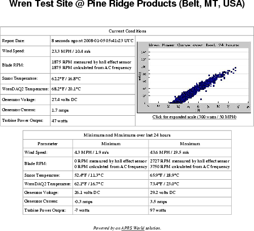
This is a screen shot of a web page. A PDF version is available. Note that this data represents a turbine in development and does not reflect the output of a normal production turbine.
The Standard WrenDAQ2 measures:
- Input voltage: 0-40 volts DC
- Current: -20 to 20 amps DC (available as -30 to 30 amps DC)
- AC frequency: 0 to 139 Hz (used to determine generator RPM)
- Wind speed: 0 to 100+ MPH from APRS World or NRG anemometer
- RPM: 0 to 8000 RPM using external hall effect sensor
- 0 to 5 volt input: Typically used for external temperature with a NTC thermistor
- Internal temperature: -40°C to 60+°C
The Standard WrenDAQ2 features:
- 900 MHz Frequency Hopping Spread Spectrum (FHSS) modem for license free operation in North America.
- Other wireless and wired communications options available depending upon region and customer requirements.
- Over voltage protection - safely shuts down if wind generator goes open circuit and produces high voltages.
- Rugged polycarbonate enclosure designed for turbine top applications
Purchasing Information
Standard WrenDAQ2 (900 MHz) for use in North America
The standard WrenDAQ2 package for use in North America is $1,000 USD and includes:
- WrenDAQ2 main unit.
- Wiring harness for DC, AC, and Ground connections. 4' long cable, non-terminated.
- Wiring harness for anemometer, RPM, and temperature sensor. RPM and temperature sensor are wired in place 3' from the connector. 10' wire pigtails for the anemometer.
- Maxstream XCITE-PKG 900 MHz wireless modem. Your choice of RS-232 or USB model.
WrenDAQ2 (2.4 GHz) for use in North America or Europe
The WrenDAQ2 package for use in North America or Europe is $1,400 USD and includes:
- WrenDAQ2 main unit.
- Wiring harness for DC, AC, and Ground connections. 4' long cable, non-terminated.
- Wiring harness for anemometer, RPM, and temperature sensor. RPM and temperature sensor are wired in place 3' from the connector. 10' wire pigtails for the anemometer.
- Maxstream XBEE-PRO 2.4 GHz wireless modem. Your choice of RS-232 or USB model.
Lead time for this model can be as long as six weeks!
Internet Data Service
APRS World, LLC can host your WrenDAQ2 live and historical data. Data is sent from your always on, Internet connected, computer to our server. Our server is located in New York, New York, USA and is very fast and reliable. Your data site can have unlimited views and can be made available to the public or password protected. This service is $120 USD per year.
Because there are custom code and configuration required for your data, we charge a $100 setup fee. If you have a WrenDAQ2 and Wind Data Logger synchronized then the setup fee is $250.
If you wish to run your own server, APRS World can supply you with the code and database schema we use for our system. This has the same setup fee as our hosted service, however there is no reoccurring fee from APRS World.
Customization
The WrenDAQ2 was developed to meet the needs Chinook Turbines / Pine Ridge Products. We are offering it as an off-the-shelf product or as the basis for a custom device device to meet your specifications. If you are inquiring about a custom version we need at least the following information:
- Application Information.
- Input information. For each channel we will need to know:
- Sensor to be connected.
- Voltages, currents, frequencies, and all electrical parameters.
- Communications required. Some options include:
- 900 MHz ISM (typically North America)
- 2.4 GHz ISM (North America, Europe, and many other places)
- RS-232
- USB
- 802.11b WiFi
- Physical packaging constraints.
- Power supply requirements.
- Required quantity.
- 1 is okay.
-
- Higher quantities have lower unit prices.
- Required by date.
- Any other applicable information. The more we know, the better.
Technical Details
Hardware Description and Schematic
WrenDAQ2 Schematic
The WrenDAQ2 circuitry is fairly simple. It consists of the following main blocks:
-
The WrenDAQ2 is based around a PIC18F2620 microcontroller. This is a small 8-bit uC with lots of flash memory and lots of RAM. The PIC is responsible for all measurements and conversion. The PIC has a 10-bit analog to digital converter and multiplexor built in. A precision 5.00 volt voltage referenced is employed.
-
Communications with the outside world is accomplished with a Maxstream / Digi xCite RF modem module. This is a 900 MHz 4mW serial modem. It basically acts as a serial cable replacement. The modem is a RP-SMA connector for connection to the 900 MHz antenna mounted on the outside of the enclosure.
-
Frequency measurement is accomplished by rectifying the AC input signal and using resistors to drop the voltage to level suitable for driving the LED in an opto-isolator. There are fuses on the board to protect the board and circuit in the event of a fault. The output of the opto-isolator is fed to the PIC and the time between falling edges of the pulse is measured. This circuit is very similar to our the circuit in our WTSS HV sensor.
-
There are four analog channels that the WrenDAQ measures: input voltage, pass-thru current, external 0-5 (typically temperature), and internal temperature. These signals are run through an RC low pass filter and buffered with a rail-to-rail op-amp. Despite being called a rail-to-rail op-amp, the filtered signals can only swing from approximately 0.05 volts to 4.95 volts. The RC network that comprises the filter has R=15.8k and C=10uF which leads to a cutoff frequency Fc=10 Hz.
-
The PIC has three external interrupts which are used by the WrenDAQ2 for external counters / timers. These are used by: Anemometer, RPM sensor, and frequency of AC signal. The external interrupts are implemented in the PIC using schimdt triggers. To prevent contact bounce with mechanical switches, a RC low-pass filter is present for each input. The RC network has R=2.2k and C=0.1uF which leads to Fc=723Hz. Before the filter there is a 4.7k pull-up resistor to allow open collector output switches to be used. The software running in the PIC starts a millisecond counter when an interrupt is fired by the falling edge of the input.
-
Internal temperature of the WrenDAQ2 is measured with an LM335 integrated circuit temperature sensor. The temperature observed by the sensor is usually warmer than outside air temperature due to heat sources inside the WrenDAQ2 enclosure. External temperature is typically measured with a 10k NTC thermistor. Here is a software function that can be used to convert NTC thermistor voltage output to temperature:
function ntcThermistor($voltage,$beta,$beta25,$rsource,$vsource) {
	$rt=($voltage*$rsource)/($vsource-$voltage);
	$tkelvin=1.0/( (1.0/$beta)*log($rt/$beta25) + 1.0/298.15);
        return $tkelvin;
}
Where:
- $voltage is the measured voltage
- $beta is the beta value for the thermistor
- $beta25 is the resistance at 25°C
- $rSource is the pullup resistor in the resistor / thermistor voltage divider
- $vsource is the excitation voltage of the voltage divider
For the WrenDAQ2 with a normal 10k thermistor these values are:
- $beta=3977
- $beta25=10000
- $rsource=4700
- $vsource=5.0
-
Power for the WrenDAQ2 is pulled from the DC wires that passthru for current measurement. The WrenDAQ2 uses two voltage regulators. A switching regulator takes 10 to 40 volts and converts it to 8 volts DC. A linear regulator takes 8 voltages and regulates it 5 volts DC. Most of the circuitry runs off of this 5 volt power supply. A precision resistor divider scales the 0 to 40 volt input to 0 to 5 volts suitable for input to the analog to digital converter. A crowbar voltage clamp is implemented after a self resetting fuse. If the voltage goes above the zener diode voltage (typically 36 volts), an SCR will fire and short out the input voltage rail. The self resetting fuse will trip and power will cycle. This results in a device that is protected from most over voltage situations. A side-effect is that the WrenDAQ2 typically not operate with an open circuit wind generator.
-
Current is measured by the WrenDAQ2 using a hall effect current sensor chip from Allegro. Allegro makes a number of devices in a SOIC8 package that can measure from +- 5 amps to +- 30 amps. Depending upon the application the WrenDAQ2 can be manufactured with any of these sensors. The current sensor outputs a voltage that is proportional to current flowing through the chip. With no current flowing through the chip the sensor will output Vsupply/2 or 2.5 volts. With maximum current flowing from IP+ to IP- the sensor will output 4.5 volts and with maximum current flowing from IP- to IP+ it will output 0.5 volts.
Internal Photos and Description
More photos can be found at in the WrenDAQ2 Gallery.
|
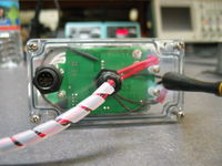
Bottom cover of the WrenDAQ2. The weatherproof connector on the left is for connecting the external temperature sensor, anemometer, and RPM sensor. The middle feedthru is for DC, AC (to pickup frequency), and ground. The antenna on the left is for the 900 MHz ISM modem.
|
|
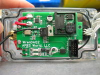
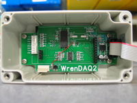
One of two WrenDAQ2 circuit boards. This board has a current sensor (marked U1), a switching power supply module (marked U2), crowbar over voltage protection, and a AC frequency pickup. It connect to the other circuit board with a 10 pin ribbon cable plugged in to J2. The brass hardware on the left attaches the 900 MHz antenna. The white wires on the right are to the weatherproof sensor connector.
|
|
WrenDAQ2 main circuit board. There is a PIC18F2610 microcontroller (U5) in the center of the board. The passive parts on the left are low-pass filters for the anemometer and RPM inputs. The passive parts at the op-amp (U3) are low pass filters for the analog inputs. There is an onboard temperature sensor (U4). On the right is a point-of-load regulator that takes the 8 volts from the switching power supply on the other board and regulates to 5 volts. U6 is a precision 5.00 voltage reference for the ADC.
|
|