Introduction:
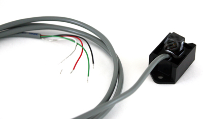
Our temperature and relative humidity sensor is high quality and low cost. We utilize a precision calibrated sensor module and surround it with tough interface electronics and a rugged potted case. The sensor can measure temperature from -26°C to 70°C (-15°F to 158°F) and relative humidity from 3% to 100%. The sensor comes standard with a 2 meter (6 foot) shielded cable with wire leads.
Photos of the sensor in action can be found in the photo gallery.
Specifications:
| Temperature | |
|---|---|
| Range: | -27°C to 70°C |
| Accuracy: | ± 0.5°C typical |
| Response Time: | 50 seconds in slow moving air |
| Relative Humidity | |
| Range: | 3% to 100% non-condensing |
| Accuracy: | ± 2% RH typical |
| Linearity: | ± 0.5% RH |
| Hysteresis: | ± 1% RH, maximum |
| Temperature Coefficient: | ± 0.008% RH / °C, maximum |
| Response Time: | 25 seconds in slow moving air at 25°C |
| Recovery Time (from condensation): | 10 seconds |
| Stability: | ± 0.5% RH per year |
| Electrical Specifications | |
| Input Voltage: | 4 to 6 volts DC |
| Weight and Dimensions | |
| Weight: | 106 grams (3.7 ounces) including 3 m (10 ft) cable |
| Dimensions: | 35 mm wide, 26 mm tall, 26 mm deep (1 x 1 x 1.4 in) not including cable |
Pricing:
|
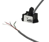
Temperature and relative humidity sensor, 2 m (6 ft) cable
|
|
 Click on photo to enlarge
|
US Price: $138.00 USD Please call us at +1-507-454-2727 to place an order. Or click here to order online from Sensor measures temperature and relative humidity. Includes a 2 m (6 ft) shielded cable with wire leads. Part Number: APRS6577 Shipping Weight: 0.25 pounds RoHS: compliant Origin: USA 

|
|
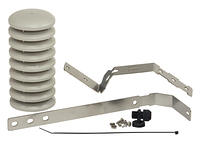
Solar radiation shield
|
|
 Click on photo to enlarge
|
US Price: $40.00 USD Please call us at +1-507-454-2727 to place an order. Or click here to order online from Solar radiation shield for temperature sensor or for temperature and relative humidity sensor. Provided as an easy to assemble kit. A variety of mounting options are possible. Can be mounted to a wall or structure with customer supplied mounting screws. Can also be mounted to a pole or mast with customer supplied hose clamps. Shield Dimensions (W x H): 76 mm x 152 mm (3 in x 6 in) Part Number: APRS6547 Shipping Weight: 1.00 pounds RoHS: compliant Origin: USA
|
Technical Details:
Schematic
A schematic is available.
Wind Data Logger Configuration
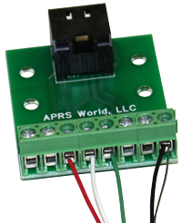
The temperature and relative humidity (tempRH) is plugged into the "TEMP&ADC" connector on the Wind Data Logger. You will need our RJ-45 Breakout Board to Screw Terminals to connect to our data loggers. The self contained data loggers have a breakout board built in. The sensor should be hooked up like the photo on the right (click for larger image)::
The wire color information is as follows:
| Black | Ground |
|---|---|
| Red | +4 to +6 VDC |
| White | Temperature Signal (0 to 3.3 VDC) |
| Green | Relative Humidity Signal (0 to 3.3 VDC) |
| Silver | Shield |
A typical connection to the Wind Data Logger's "Temp & ADC" Connector would be as follows:
| Black | Pin 2 or 8 (Ground) |
|---|---|
| Red | Pin 3 (+5 Volts) |
| White | Pin 4 (Analog 4) |
| Green | Pin 5 (Analog 5) |
| Silver | Pin 2 or 8 (Ground) |
To display actual sensor readings on the Wind Data Logger you will need to configure the ADC channels. The following equations are used to convert the voltage output from the sensors to standard units:
Temperature:
°C=39.394*Vin - 30.0 (ADC M: 39.394 / ADC B: -30.0 / ADC Units: C)°F=70.9092*Vin - 22.0 (ADC M: 70.9092 / ADC B: -22.0 / ADC Units: F)
Relative Humidity:
%RH=30.303*Vin (ADC M: 30.303 / ADC B: +0.0 / ADC Units: %)The values in parenthesis should be entered into the ADC setup screens on the Wind Data Logger.
Stabilization Time
The sensor requires a stabilization period of up to 10 minutes after powering up the sensor. Upon applying power, the sensor will initially output a signal of 0 volts. After a short time, the signal voltages will start to rise until they eventually stabilize on the current ambient conditions.
Mounting
The sensor electronics are potted in a flexible polyurethane potting compound inside a small ABS plastic potting box. This protection allows the sensor to be used indoors with no additional protection. For outdoor use the sensor must be protected from direct moisture contact. For accurate temperature and relative humidity readings the sensor must have air flowing over it. We recommend that the sensor be protected by a solar radiation shield. APRS World sells a solar radiation shield, or a shield may be homebrewed or purchased from another source.
| Dimension | Inches | Millimeters |
|---|---|---|
| Length (A) | 1.0 | 25.4 |
| Width (B) | 1.0 | 25.4 |
| Height (C) | ~1.0 | ~25.4 |
| Mounting Flange Length (E) | 1.88 | 47.8 |
| Mounting Flange Holes (F) | 1.375 | 34.93 |
| Mounting Hole Diameter | 0.184 | 4.7 |
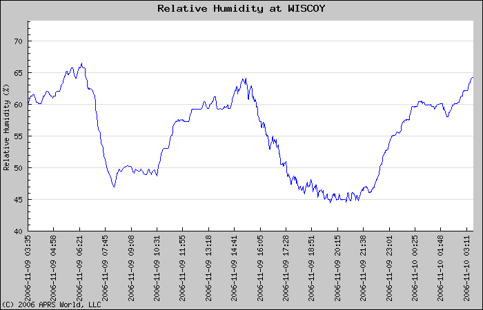
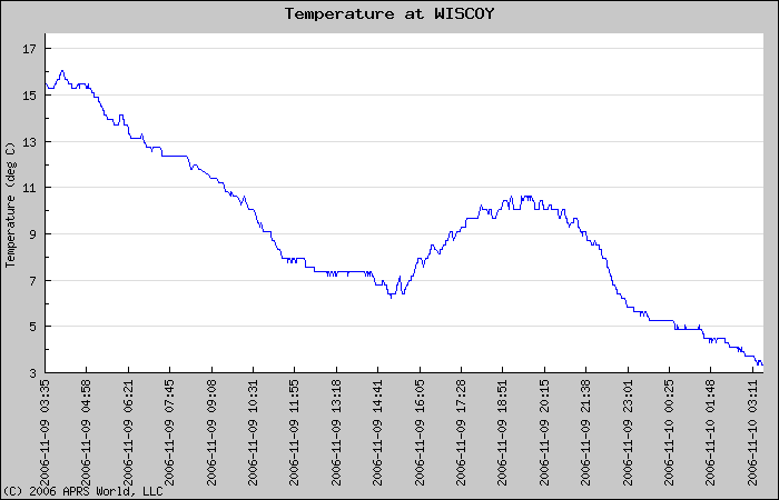
Example Data:
The following data was captured on 2006-11-09 near Winona, Minnesota, USA. Weather conditions observed at the local airport can be found at:http://www.wunderground.com/history/airport/KONA/2006/11/9/DailyHistory.html
Note that the local airport is approximately 15 miles distant.
Temperature Plot
Relative Humidity Plot